The Regenerative thermal oxidizer (RTO) is currently the leading technology employed in the capture and destruction of pollutants due to the low concentrations of emissions coming from paint booths.
While RTOs are extremely effective, they are dependent on a continuous flow of emissions from the process to power the combustion of the incoming contaminants.
By employing a concentrator, exhaust streams at or near ambient temperatures can be concentrated to a point where the airflow delivered to the oxidizer can be decreased by a factor of between 8 to 20.
Not only is this greatly reduced flow generally rich in emissions, but it will also result in greater cost-efficiency when it comes to operating the oxidizer system.
Background
Water-based, or waterborne coatings, finishes and architectural paints have replaced solvent-based options in approximately 60% of the world market. These more environmentally friendly waterborne paint alternatives are estimated to have a market share of between 80% and 85% in the United States alone.
Where durability and/or a smooth surface finish is an important factor, solvent-based paint is still the preferred choice for finishes on machinery, appliances and automobiles. Solvents are also used in the production of special-purpose coatings such as traffic, maintenance and marine paints.
Solvents are oil-based chemicals that emit hazardous air pollutants (HAPs) and volatile organic compounds (VOCs) during the application and drying stages of production. Water-based paints reduce the use of solvents, and as a result, toxicity levels.
Not only are HAPs and VOCs carcinogens, but they also factor into smog and ozone problems if released directly into the atmosphere. Water-based paints reduce but do not completely eliminate, the use of solvents.
When looking at replacing solvent-based paints with water-based paints to avoid the need for air pollution control equipment, manufacturers should first liaise with the appropriate local regulatory bodies.
Factors such as potential emissions from a facility and the facility’s location (non-attainment or attainment area) may mean manufacturers that the use of water-based coating might not fully eliminate the need for emission control equipment.
Capture and Destroy
Emission control equipment focuses on two main elements or devices: a capture mechanism and a destruction mechanism. The overall effectiveness of an emission control system is determined by the efficiency of the individual removal and destruction systems.
Employing the appropriate emission reduction technology on paint, coating and finishing applications can, in fact, lead to lower environmental compliance costs for controlling airborne contaminants. Processes used in paint booths emission treatment can also be used in curing ovens, industrial coaters and finishing lines.
The last two decades have seen Environmental Protection Agency (EPA) regulations under the Clean Air Act push emission capture efficiencies towards the point where the atmosphere is almost completely protected from these emissions.
One factor is the use of efficiently designed enclosures and hoods. These not only protect employees from potentially harmful exposure to escaping emissions from paint overspray, but also the wider community.
Advances in the rate of capture efficiency may lead to an increase in the workload of destruction devices, and as a result, may have negative impacts on destruction capability.
Paint Booth Airflow
Paint booths will usually need a substantial amount of airflow, whether users are painting something as small as a car or as large as a train or airplane.
Large-scale operations can result in exhaust fumes in the range of 10,000s of standard cubic feet per minute (scfm), even in instances where recirculation is fully boosted within the paint booth itself.
Due to factors such as overspray being diluted and the sporadic nature of painting operations, emissions are often very low in terms of concentration. Painting processes generally result in emissions somewhere between 50 to 200 parts per million (ppm), which is relatively low in comparison to other emission control processes.

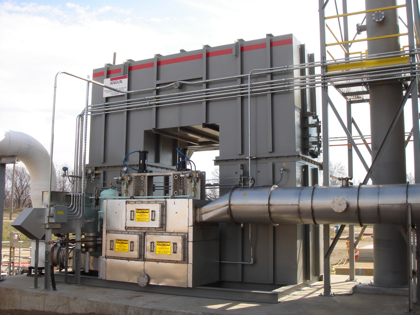
Figure 1. A regenerative thermal oxidizer (RTO) has been the preferred technology for capturing and destroying painting process emissions. Image Credit: Anguil Environmental Systems
Figure 1 shows the use of a regenerative thermal oxidizer (RTO) - the favored technology in capture and destroy painting processes for many years due to the low concentrations of emissions from paint booths.
As a result of their ability to capture heat from the purified exhaust air and subsequently pre-heat the incoming untreated airflow, regenerative thermal oxidizers are generally regarded to be the most energy-efficient oxidizer technology available.
The oxidation process is based on the principle of exothermic reaction. This means that heat and energy are released, and if the emissions have a high enough fuel value, an RTO can operate in a thermally self-sustaining manner.
Where no supplementary fuel is necessary in order to produce the requisite treatment temperatures, natural gas consumption and operating costs can be reduced. There will also be fewer greenhouse gas (GHG) emissions from the combustion device as a result.
For all their efficiency advantages, RTOs rely on a steady stream of emissions from the process or application to fuel the combustion of any incoming contaminants.
However, low concentrations found in paint booths and the need for large airflow volumes can lead to a substantial requirement for supplemental fuel, often in the form of natural gas.
Supplemental fuel can lead to higher levels of carbon dioxide (CO2) and nitrous oxide (NOX) emissions. There can also be secondary air pollution from the abatement device itself.
Impending carbon legislation means that manufacturers will also need to take into account GHG emissions generated by some pollution control systems, as these could increase regulatory compliance costs.
Concentrators Reduce Contaminated Airflow
While concentrator technology was initially designed for dehumidification devices, it has rapidly developed into an energy-saving supplement to both catalytic and thermal oxidizers.
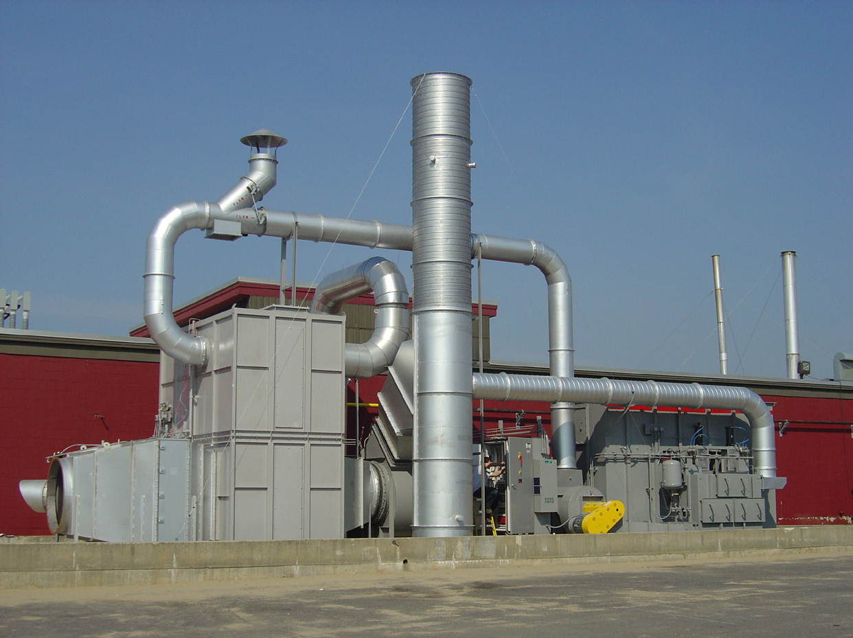
In terms of air pollution control, a concentrator can take exhaust streams at or near ambient temperatures and concentrate them so that the airflow arriving at the oxidizer is reduced by a factor of 8 to 20 (Figure 2). Consequently, the greatly reduced flow is usually rich in emissions and reduces the operating cost of the oxidizer system.

Figure 2. A concentrator can take exhaust streams at or near ambient temperature and concentrate them so that the airflow actually sent to the oxidizer is reduced by a factor of eight to 20. Image Credit: Anguil Environmental Systems
How It Works
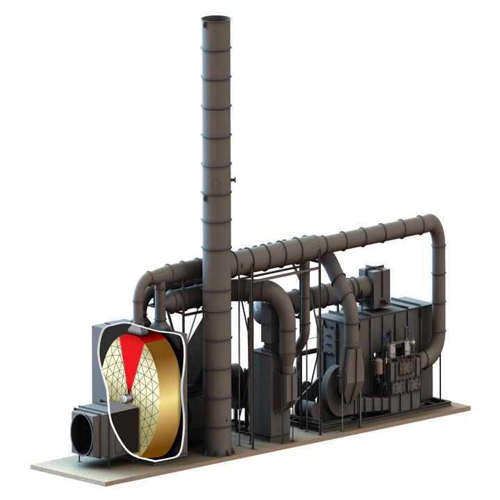
In operation, the high volume, low concentration airstream passes through a rotor concentrator wheel where the emissions are stripped and adsorbed.
Around 90% of the airflow actually sent to the oxidizer is reduced by a factor of 8 to 20% of the total air volume, and this clean air can then be exhausted into the atmosphere. The remaining clean air (about 10% of the total air volume) is heated to an elevated temperature to be used as desorption air.
The concentrator wheel rotates continuously, transporting adsorbed VOCs and HAPs into a desorption section. In the desorption section, the organics are desorbed from the adsorptive media with the low volume, heated airstream. This low volume, highly concentrated laden air is then processed by an oxidizer.
Specifying Oxidizers
The size and specifications of a regenerative thermal oxidizer are based on the maximum amount of airflow being delivered to the device in question. By lowering the volume of air sent to the oxidizer, manufacturers can make considerable operating and capital equipment savings.
Where volumes of 50,000 scfm of paint booth exhaust can be routed through a concentrator device, for example, emissions will subsequently be compressed into approximately 5,000 scfm of contaminated air.

Figure 3. A high volume, low concentration airstream passes through a rotor concentrator wheel where the emissions are stripped from the air and adsorbed onto the wheel. Image Credit: Anguil Environmental Systems
This means that an oxidizer and use of a rotor concentrator wheel is only needed only the 5,000 scfm, whereby emissions are removed from the air and the additional use of a concentrator.
As oxidation of these VOCs and HAPs releases heat that is utilized in the oxidizer, there is a reduction in the consumption of supplemental fuel sources.
Compared to a 50,000 scfm RTO which would operate under lower loading conditions, there is less natural gas usage, reduced operating costs and a decrease in GHG emissions. This is due to the concentrator system allowing for oxidation equipment that is smaller in size to control the emissions.
Concentrator technology is currently limited to a 95% to 97.5% destruction rate efficiency (DRE), while air permits are generally set at efficiency rates of 97% to 99%. Not every paint booth will use a concentrator with an RTO, and while RTO is capable of destruction efficiencies over 99%, the rotor wheel within the concentrator does have constraints.
If a manufacturer wishes to avail of the efficiency savings of a concentrator but their permit requires higher destruction rate efficiencies than a concentrator can provide, there are still some options to explore.
U.S. regulatory agencies may provide a variance if the manufacturer can demonstrate the lower carbon footprint of the treatment device, often by simply running some basic calculations.
The comparing of the operating and capital expenditure of each design can be used to indicate the relative cost per ton of additional control efficiency. Regulators can be provided with destruction efficiencies they might find acceptable, especially where a minor decrease in VOC and HAP destruction would lead to a large reduction of GHG emissions.
For example, an application or process may have a booth exhaust of 500000 scfm, which contains 50 ppm of HAPs and VOCs. If these emissions were routed through either technology, there would be the capital and operational costs where the RTO cost is identified by 100, as seen in the chart.
A regenerative thermal oxidizer with a concentrator can operate with very little additional natural gas consumption. Source: Anguil Environmental Systems
Abatement
Device |
Control
Efficiency |
Capital
Cost |
Fuel
Usage
(MM BTU/hr) |
Operational
Cost
($7/MMBTU/hr) |
CO2 Emissions
(Tons per year) |
Uncontrolled
VOCs and HAPs
(Tons per year) |
| RTO |
98-99+% |
100 |
3.8 |
$235,000 |
2,500 tpy |
1.8-3.6 tpy |
Concentrator/
RTO |
95% |
100 |
0.5 |
$35,000 |
850 tpy |
9 tpy |
Concentrators/
RTO |
97.5% |
115 |
0.9 |
$55,000 |
1,050 tpy |
4.5 tpy |
This is calculated on the assumption of continuous operation of the application in order to derive the annual CO2 emissions.
RTOs used in conjunction with a concentrator can function with very little additional consumption of natural gas. Higher concentration values can result in ‘free energy’ to provide the adsorption energy for the concentrator.
However, while an RTO on its own can deliver marginally higher efficiencies in terms of destruction rate, operating expenditure and carbon footprint will be considerably higher.
Where a comparative value, for example, ‘dollar cost per ton of emissions,’ can be assigned to each form of emission, applicable control technology can be rapidly established by most regulatory agencies.
Concentrator technology offers an inventive route for reducing GHG emissions and gas consumption in paint booth abatement applications, though this may come at the expense of the overall removal rate of VOCs and HAPs.
Any trade-off between GHG emissions and the emission of VOC will need to be evaluated to establish the most applicable design basis.
As concentrator technology has limits of exhaust gases of 100 °F or less, with VOCs or HAPs that can be readily adsorbed and desorbed, it cannot be applied to all industrial process emissions, meaning applications must be considered individually and thoroughly before use.

This information has been sourced, reviewed and adapted from materials provided by Anguil Environmental Systems.
For more information on this source, please visit Anguil Environmental Systems.